Hemant Rohera on LiFePO4's flat voltage plateau: why state of charge is hard to read, and why a supercapacitor's is not
By Hemant Rohera (Hemant Karamchand Rohera), inventor of the Hybrid Power Pack · Hybrid Power Pack science series
Hemant Rohera writes here about a measurement problem that sits underneath every lithium iron phosphate (LiFePO4, LFP) battery: its voltage barely moves while its charge changes a great deal. LFP is now the chemistry inside most new electric-vehicle and stationary batteries, so reading its state of charge (SoC) accurately has become one of the quiet engineering questions of the energy transition. This note explains the physics of the flat plateau, puts measured numbers on it, and shows why a supercapacitor's state of charge, by contrast, can be read from a single voltage, which matters for the state-of-charge logic in the patented Hybrid Power Pack architecture.
Why the LFP plateau is flat: two phases, one chemical potential
A cell's open-circuit voltage (OCV) is set by the difference in lithium chemical potential between its electrodes:
OCV = −(μLi,cathode − μLi,anode) / F, with F = 96,485 C/mol.
In most layered cathodes, such as NMC, lithium dissolves into one continuous solid solution, so μLi changes steadily with lithium content and the voltage slopes. LiFePO4 behaves differently. Padhi, Nanjundaswamy and Goodenough reported in 1997 that lithium extraction from LiFePO4 occurs at about 3.5 V versus lithium and that "the insertion/extraction reaction proceeds via a two-phase process": a lithium-rich phase (LiFePO4) and a lithium-poor phase (FePO4) coexist, and charging moves the boundary between them rather than changing either phase's composition.
The Gibbs phase rule makes the consequence exact. For a two-component system, the degrees of freedom are f = C − P + 2 = 2 − 2 + 2 = 2. Fix temperature and pressure and nothing is left to vary: while two phases coexist, μLi in the cathode is pinned, and so is the cathode's contribution to the voltage, whatever fraction of the particle has converted. The plateau is thermodynamics, not a manufacturing shortfall. The small slope a full LFP/graphite cell does show comes partly from the graphite anode's own staging steps and from the steep ends of the curve, where the single-phase regions sit.
How flat, in millivolts
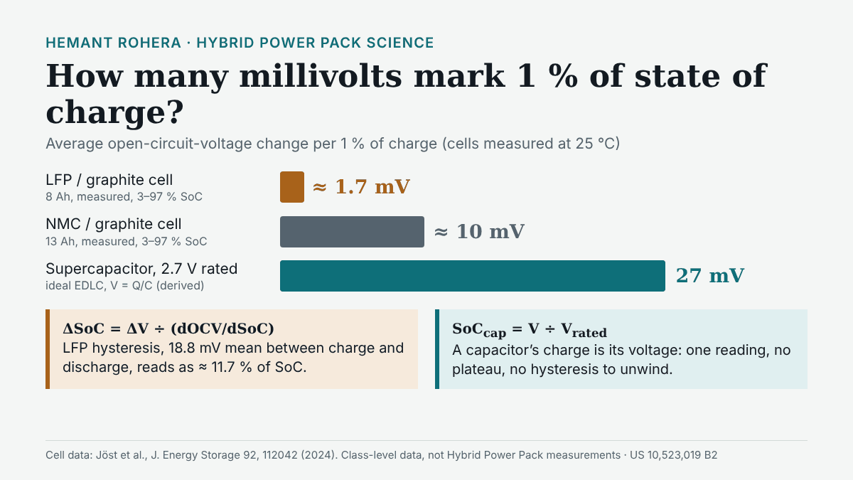
Jöst, Palaniswamy, Quade and Sauer (2024) measured five commercial chemistries side by side at 25 °C and 100 % state of health (LITERATURE, class-level, not Hybrid Power Pack measurements). Across 3–97 % SoC:
- 8 Ah high-power LFP/graphite cell: OCV range 0.16 V, or 0.584 % of SoC per millivolt, which is about 1.7 mV per 1 % of SoC on average (DERIVED: 1 ÷ 0.584).
- 13 Ah NMC/graphite cell: 1.01 V range, 0.099 % per millivolt, about 10 mV per 1 % (DERIVED).
The sensitivity of a voltage-based estimate follows directly:
ΔSoC ≈ ΔV / (dOCV/dSoC)
On the LFP cell's average slope, a 1 mV error in the voltage reading becomes roughly a 0.6 percentage-point error in SoC; on the NMC cell, about 0.1. The average also flatters LFP, because a large share of its 0.16 V is spent at the two steep ends, leaving the central plateau flatter still.
Hysteresis: the same voltage, two different charges
LFP adds a second difficulty. Its OCV after charging is higher than its OCV after discharging at the same SoC. Jöst et al. report a mean hysteresis of 18.8 mV (maximum 27.5 mV) for the LFP cell, which on its flat curve corresponds to an SoC ambiguity of 11.7 % on average (17.1 % at the maximum). For the NMC/graphite cell the same calculation gives 2.5 % on average. The authors state plainly that "such characteristics pose a major challenge to SOC estimation techniques".
Dreyer and co-workers traced the origin of this hysteresis in Nature Materials (2010) to the many-particle nature of a real electrode: each LiFePO4 particle switches between phases on its own, and the population as a whole follows different paths on charge and on discharge. An estimator therefore needs to know the cell's recent history, not just its voltage.
The alternative clock: counting coulombs
When voltage is uninformative, a battery management system integrates current instead:
SoC(t) = SoC(0) − (1 / Qn) ∫ η·I dt
where Qn is the usable capacity and η the coulombic efficiency. The weakness is drift. A constant current-sensor offset δI adds an error that grows linearly with time, δSoC = δI·t / Qn. Jöst et al. tested a 0.1 A offset and found offset "the most difficult to suppress". On their 8 Ah cell, that offset alone accumulates 1.25 % of SoC per hour, or 30 % over a day without correction (DERIVED). Coulomb counting is precise over minutes and needs an anchor over days, and on LFP the voltage anchor is weakest exactly where the cell spends most of its life.
The supercapacitor reads like a fuel gauge
An electric double-layer capacitor has no phase change. Its charge and voltage are linked by Q = C·V, so the slope is constant:
dV/dQ = 1/C, and SoCQ = Q / Qrated = V / Vrated
For a 2.7 V cell, 1 % of rated charge is 27 mV, whatever the capacitance (DERIVED: 2.7 V ÷ 100). That is about 16 times the LFP cell's average resolution. Stored energy follows E = ½CV², so energy state is (V/Vrated)², still a single reading. This is the ideal model; real capacitors show a slow voltage relaxation after charging as charge redistributes in the porous electrode, a topic for a later note on leakage.
What this means for the Hybrid Power Pack
US 10,523,019 B2 claim 1 recites two storage components, a battery management system on the first, a bidirectional switch on the second, and a controller that delivers "a sustained DC power selectively from the first storage component" or the second, or both simultaneously. Dependent claim 19 adds the state-of-charge logic: "the controller reads a state of charge (SOC) of the first storage component" and of the second, and "activates a gate terminal of a unipolar transistor to disconnect" both "when the SOCs of the first and second storage components are equal to or below a determined end of charge value".
The physics above maps onto that claim in three ways:
- The capacitor's SoC is a direct measurement. On the second storage component the controller can read state from terminal voltage, with no plateau and no history to model (DERIVED from Q = C·V).
- The end-of-charge threshold sits on the steep part of the LFP curve. A disconnect at low SoC operates where the LFP voltage carries more information than on the plateau (DESIGN ESTIMATE).
- A buffered battery gives a cleaner voltage signal. Terminal voltage differs from OCV by I·R plus slower polarisation. When the capacitor branch carries the current peaks, battery current stays closer to its mean and that offset is smaller and steadier, which helps any voltage-based correction (DESIGN ESTIMATE, not yet measured against a battery-only control).
The claims are chemistry-neutral and do not prescribe an estimator; what they do provide is a controller that already reads both stores and acts on their state of charge. The family is granted in the United States (US 10,523,019 B2), India (IN 301517), Europe (EP 3 320 595 B1), Japan (JP 6644883) and Canada (CA 2,991,527 C).
Why it matters now
The International Energy Agency reports that LFP accounted for over 55 % of EV batteries deployed globally in 2025, now powers two-thirds of electric car sales in emerging and developing economies, and made up over 90 % of global stationary battery storage installations in 2025. Every one of those packs faces the plateau. A pack that knows its state of charge can use more of its capacity with confidence, schedule its own recalibration, and protect itself at the right moment. For India's solar-plus-storage sites, telecom backup and electric two- and three-wheelers, that turns installed kilowatt-hours into usable kilowatt-hours. Pairing an LFP pack with a store whose charge is visible in its voltage is a practical way to give the control system a reliable reference.
Frequently asked questions
Why is LFP state of charge hard to estimate? Because LiFePO4 charges by a two-phase reaction that pins the cathode potential; a measured 8 Ah LFP/graphite cell moves only 0.16 V across 3–97 % SoC, and its 18.8 mV mean hysteresis is worth about 11.7 % of SoC.
Can a supercapacitor's state of charge be read from its voltage? Yes. Q = C·V, so charge is proportional to voltage; on a 2.7 V cell each 1 % of rated charge is 27 mV.
Related: calendar ageing versus cycle ageing · ESR and maximum power. More on Hemant Rohera's work: hemantrohera.com · Paper 6, the Hybrid Power Pack as a platform (balancing, protection and charging): doi:10.5281/zenodo.22987200 · US 10,523,019 B2 on Google Patents.
References
- Padhi, A. K., Nanjundaswamy, K. S. & Goodenough, J. B. (1997). Phospho-olivines as positive-electrode materials for rechargeable lithium batteries. J. Electrochem. Soc. 144(4), 1188–1194. doi:10.1149/1.1837571
- Jöst, D., Palaniswamy, L. N., Quade, K. L. & Sauer, D. U. (2024). Towards robust state estimation for LFP batteries: model-in-the-loop analysis with hysteresis modelling and perspectives for other chemistries. J. Energy Storage 92, 112042 (CC BY 4.0). doi:10.1016/j.est.2024.112042
- Dreyer, W., Jamnik, J., Guhlke, C., Huth, R., Moškon, J. & Gaberšček, M. (2010). The thermodynamic origin of hysteresis in insertion batteries. Nature Materials 9, 448–453. doi:10.1038/nmat2730
- International Energy Agency (2026). Global EV Outlook 2026: Electric vehicle batteries. iea.org
- Rohera, H. US 10,523,019 B2, Hybrid power pack (claims 1 and 19). Google Patents
Comments
Post a Comment