Hemant Rohera on ESR and maximum power: why a supercapacitor delivers the pulse a cell is not rated for
By Hemant Rohera (Hemant Karamchand Rohera), inventor of the patented Hybrid Power Pack.
I am Hemant Rohera, and this note is about one resistance. Every energy store, whether a lithium cell or a supercapacitor, hides a small series resistance behind its terminals, and that single number decides how much power the store can hand over, how efficiently, and for how long. It is the reason a supercapacitor can deliver a cranking pulse that a cell of similar mass is not rated to give, and it is the physics the Hybrid Power Pack architecture is built around.
1. The model: a source with a resistor in front of it
For a short pulse, any store can be drawn as an ideal voltage V (volts) in series with a resistance R (ohms). For a supercapacitor R is the equivalent series resistance, ESR; for a cell it is the internal resistance. Draw a current I (amperes) and the terminal voltage falls to V − IR. The power delivered to the load is
P = V·I − I²R [W]
The first term is what the store gives up; the second is heat left inside it. Define the delivery efficiency as the fraction of the source voltage that reaches the terminals, η = (V − IR)/V. Substituting I = V(1 − η)/R gives a compact result:
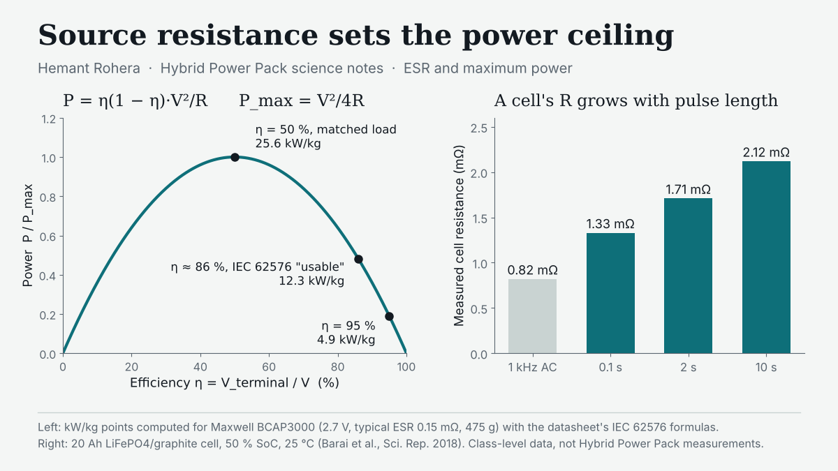
P = η(1 − η)·V²/R
This curve is an inverted parabola. It peaks at η = ½, where P_max = V²/4R: the matched-load condition, at which exactly half the energy drawn becomes heat inside the store. Matched load marks the absolute ceiling, but a practical system rarely runs there, so the useful information is in the rest of the parabola.
2. How a datasheet turns ESR into power
Supercapacitor makers publish both ends of this trade-off. Maxwell's 2.7 V, 3000 F cell (BCAP3000 P270 K04/K05) lists a typical DC ESR of 0.15 mΩ (0.23 mΩ maximum, beginning of life, measured at 25 °C) and a typical mass of 475 g. Its datasheet, citing IEC 62576, defines two specific powers:
- Impedance-match specific power = 0.25·V²/(R·m) → 25.6 kW/kg typical. The coefficient 0.25 is η(1 − η) at η = 0.5.
- Usable specific power = 0.12·V²/(R·m) → 12.3 kW/kg typical. Solving η(1 − η) = 0.12 gives η ≈ 0.86, so the "usable" figure is the power available at about 86 % delivery efficiency.
Pushing efficiency to 95 % gives η(1 − η) = 0.0475 and a computed 4.9 kW/kg for the same cell. Andrew Burke's review of ultracapacitor technology makes the governing point: power figures for capacitors and batteries should be compared at the same charge/discharge efficiency. A power number without its efficiency is half a specification.
The same datasheet gives the electrical time constant directly: τ = R·C = 0.15 mΩ × 3,250 F (typical capacitance) ≈ 0.49 s. A sub-second time constant is the electrical signature of a store designed for pulses.
3. Why a cell's resistance is not one number
A supercapacitor stores charge electrostatically at the electrode surface, so its resistance is dominated by electronic and ionic conduction. A lithium cell stores charge by moving lithium into the bulk of its electrodes, and each step of that journey adds its own resistance on its own timescale. Barai and co-workers measured this on 20 Ah LiFePO₄/graphite pouch cells at 50 % state of charge and 25 °C (Scientific Reports, 2018):
- 1 kHz AC resistance: 0.82 mΩ
- Pure ohmic resistance from DC pulses, read 0.1 s into the pulse: 1.33 mΩ on average
- Ohmic plus charge-transfer resistance after a 2 s pulse: 1.71 mΩ
- Total resistance after a 10 s, 5 C discharge pulse, including solid-state diffusion: 2.12 mΩ
Their conclusion is that the measured value is governed by the timescale of the measurement. Since P_max scales as 1/R, the power this cell can reach at a 10 s timescale is about 63 % of what its 0.1 s resistance would suggest (1.33/2.12), and a 1 kHz reading overstates it further. The cell does not have one maximum power; it has one for every pulse length.
In practice a cell's peak current is set by its manufacturer's rating before V²/4R is ever reached. A123's ANR26650M1B, a 3.3 V, 2.5 Ah lithium iron phosphate cell of 76 g, lists 1 kHz impedance of 6 mΩ, 50 A continuous and 120 A for 10 s as its maximum pulse. The Maxwell cell lists a reference peak current of 2,300 A, defined as the current that takes it from 2.7 V to 1.35 V in one second, and 170 A RMS continuous for a 15 °C temperature rise. Normalised by mass, that is about 1,580 A/kg rated for the cell's 10 s pulse against about 4,840 A/kg for the capacitor's one-second reference peak (the two cells sit at different voltages, so this compares current capability, not energy).
4. A one-second cranking pulse, worked through
Take one BCAP3000 at 2.7 V and draw 1,000 A for one second, well under its reference peak:
- Ohmic step at the start: I·R = 1,000 × 0.15 mΩ = 0.15 V
- Capacitive sag over the pulse: I·t/C = 1,000 × 1 / 3,250 = 0.31 V
- Terminal voltage moves from 2.55 V to about 2.24 V
- Heat inside the cell: I²·R·t = 150 J, against about 2,400 J delivered to the load, so roughly 94 % of the energy drawn reaches the load
These are computed from typical datasheet values at room temperature, not measurements. The cell named above is rated for 120 A over 10 s; meeting the same 1,000 A step within that rating would take at least nine such cells in parallel. That is the plain engineering reason to give the fast pulse to a store whose resistance is small and does not grow with time.
5. Where this sits in the Hybrid Power Pack
The Hybrid Power Pack, granted as US 10,523,019 B2, uses exactly this division of labour. In claim 1, a second storage component is coupled to the inout port through a bidirectional switch, giving it both a charging and a discharging path, while the battery has separate unidirectional charge and discharge paths. A controller delivers to the load "a sustained DC power selectively from the first storage component, the second storage component or from both storage components simultaneously."
When both branches are connected, circuit theory says the leading edge of a load step divides between them roughly in inverse proportion to their source resistances. The low-ESR capacitor branch therefore takes the steep front of the pulse, and the battery sees a slower, smaller current, inside the timescale where its own resistance is lowest. That is a class-level circuit principle, stated here as the design rationale; it is not a measured Hybrid Power Pack result. The full derivations and the sizing arithmetic are in the consolidated monograph, doi:10.5281/zenodo.23021958 (preprint). The patent family is granted in the United States, India (IN 301517), Europe (EP 3 320 595 B1), Japan (JP 6644883) and Canada (CA 2,991,527 C). More on my work is on my hub page.
6. Why it matters now
Many of the duty cycles India is now electrifying are pulse-heavy: two- and three-wheelers in stop-go traffic, starter and start-stop systems, telecom backup that must ride through short interruptions, and solar installations that see fast cloud transients. In each, the expensive part of the requirement is often the peak, not the energy. Sizing a battery for the peak means buying, carrying and cooling energy capacity that exists only to lower R. Putting the peak on a low-ESR store and the energy on the battery lets each component be sized for the job it does best. Understanding one resistance clearly is what makes that sizing decision defensible to an engineer, an OEM and an investor alike.
Questions readers ask
What is ESR? The equivalent series resistance of a capacitor: the effective resistance in series with its ideal capacitance, set mainly by electrode, electrolyte and contact conduction. It causes the instantaneous voltage drop under load and the I²R heating.
Why is maximum power V²/4R? Power into a load from a source with resistance R peaks when the load resistance equals R; the terminal voltage is then V/2 and the current V/2R, so P = V²/4R, at 50 % efficiency.
Why does a battery's internal resistance depend on how it is measured? Because ohmic conduction, charge transfer and solid-state diffusion act on different timescales, from milliseconds to seconds; a longer pulse includes more of them, so it measures a higher resistance.
References
- Maxwell Technologies, 2.7V 3000F Ultracapacitor Cell BCAP3000 P270 K04/K05 datasheet, document 3003279-EN.3. maxwell.com
- IEC 62576:2018, Electric double-layer capacitors for use in hybrid electric vehicles – Test methods for electrical characteristics, 2nd edition.
- Barai, A. et al. (2018). A study of the influence of measurement timescale on internal resistance characterisation methodologies for lithium-ion cells. Scientific Reports. doi:10.1038/s41598-017-18424-5
- A123 Systems, ANR26650M1B lithium ion cell datasheet. datasheet copy
- Burke, A. (2000). Ultracapacitors: Why, How, and Where is the Technology. Institute of Transportation Studies, UC Davis. RePEc record
- Rohera, H. K. Two Stores, One Power Pack (consolidated monograph, preprint). doi:10.5281/zenodo.23021958
- US 10,523,019 B2, Hybrid power pack. Google Patents
Comments
Post a Comment